009——Build log——Updated weekly

Progress,
in public.

A running log of what we're building, testing, and learning. Published as things happen. No polish, no press releases. The honest version.

S1 · FoundationsIn progress
Prototype + patent
S2 · ValidationQueued
Phantom testing
S3 · Pilot
Human testing
S4 · Market
Launch
Filter
Latest update

Feasibility confirmation and the future of EIT-tek

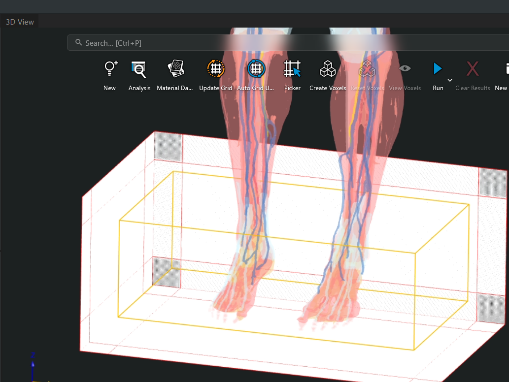
Recently the EIT-tek team has had multiple calls with researchers and investors to determine the feasibility of the product we are trying to create. The products capabilities has changed as I personally learn more about this exciting yet limited technology. The end goal stays the same, an analysis device that allows athletic trainers and athletes never before seen insight to their musculoskeletal health and recovery. After some recent meetings we have determined that our approach to solving this problem is scientifically possible and shows promise to investors. We are hard at work on creating a wearable prototype aimed for a November 2026 showcase; this demo should offer a wearable band, either for an arm or an ankle (one or the other) that users can use to demo scans. An MVP (without custom hardware) should come by the end of the year to hopefully be used in a pilot program.

#Meetings#Prototype#WeCanDoIt!!!#dev-log

Finalizing custom PCB / CrossCore Embedded Studio

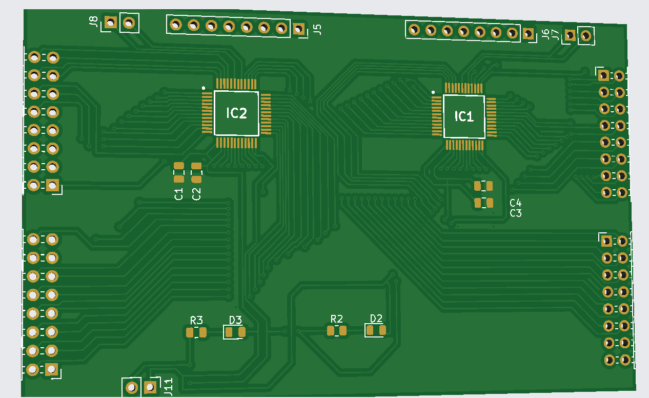
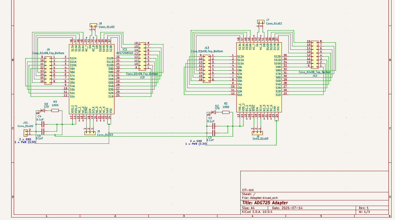
After asking reddit I found some issues with my initial circuit design. Since this is my first actual printed circuit board, I needed to worry about a lot more than just whether my circuit worked in ltSpice; I would also need to worry about the physics behind traces and the electromagnetic fields it creates and how it interacts with the other traces. Additionally I needed to worry about decoupling capacitors as to ensure a steady, consistent stream of voltage to the chip. Another thing I also forgot was "copper pours" or a ground around the entire board. I went ahead and added this to make the grounding of the decoupling capacitors easier. I have ordered and shipped the circuit board to my address and will update / experiment once I receive it. I have also started trying to figure out how to use CrossCore Embedded Studio, I have taken a class on embedded programming at RPI but I have never worked with this specific board before so there will be a bit of a learning curve!

#PCB-Design#NewSoftware#Prototype#EmbeddedHardware#dev-log

Custom MUX PCB

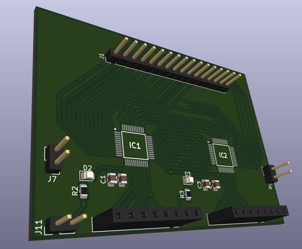
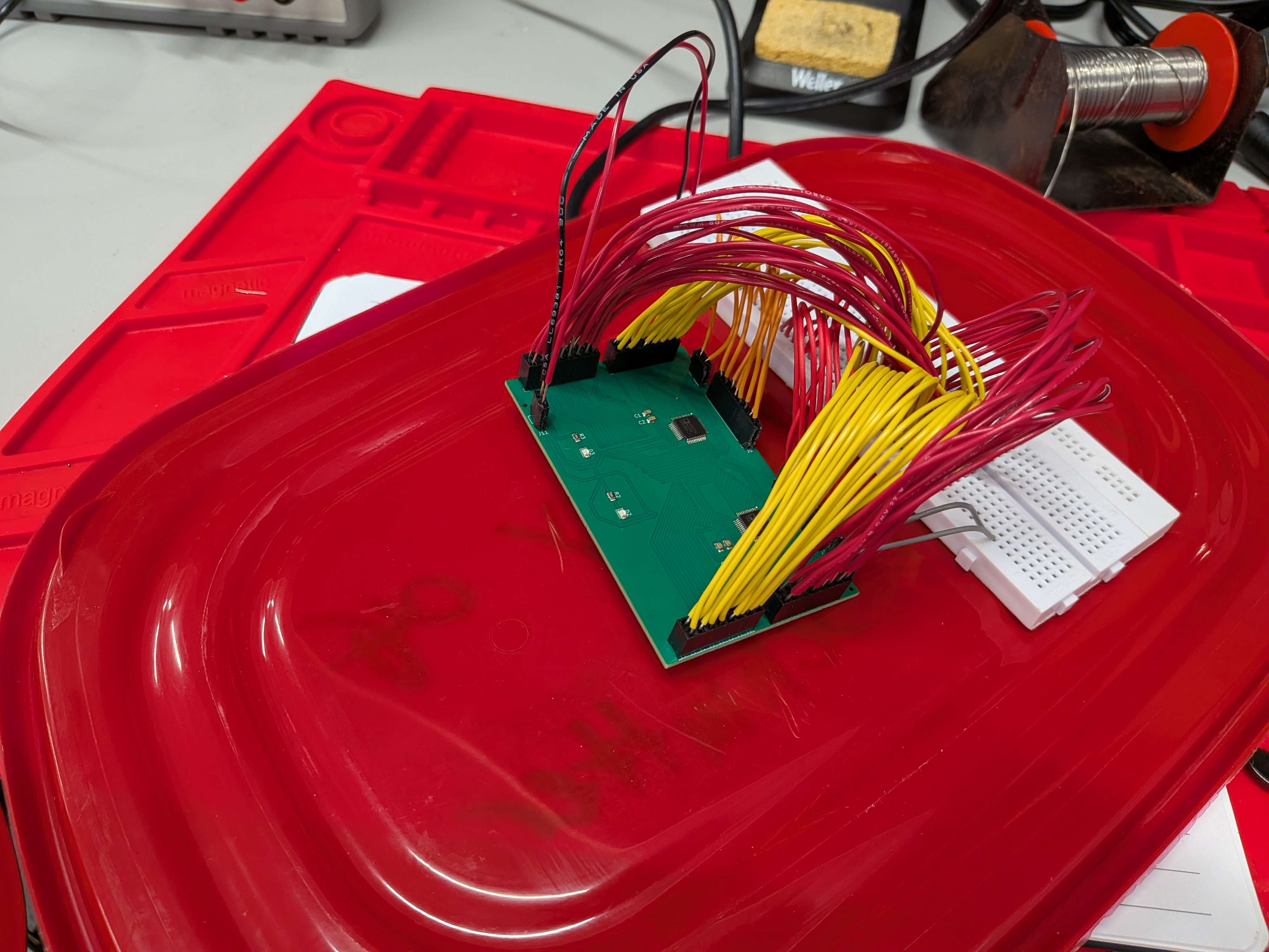
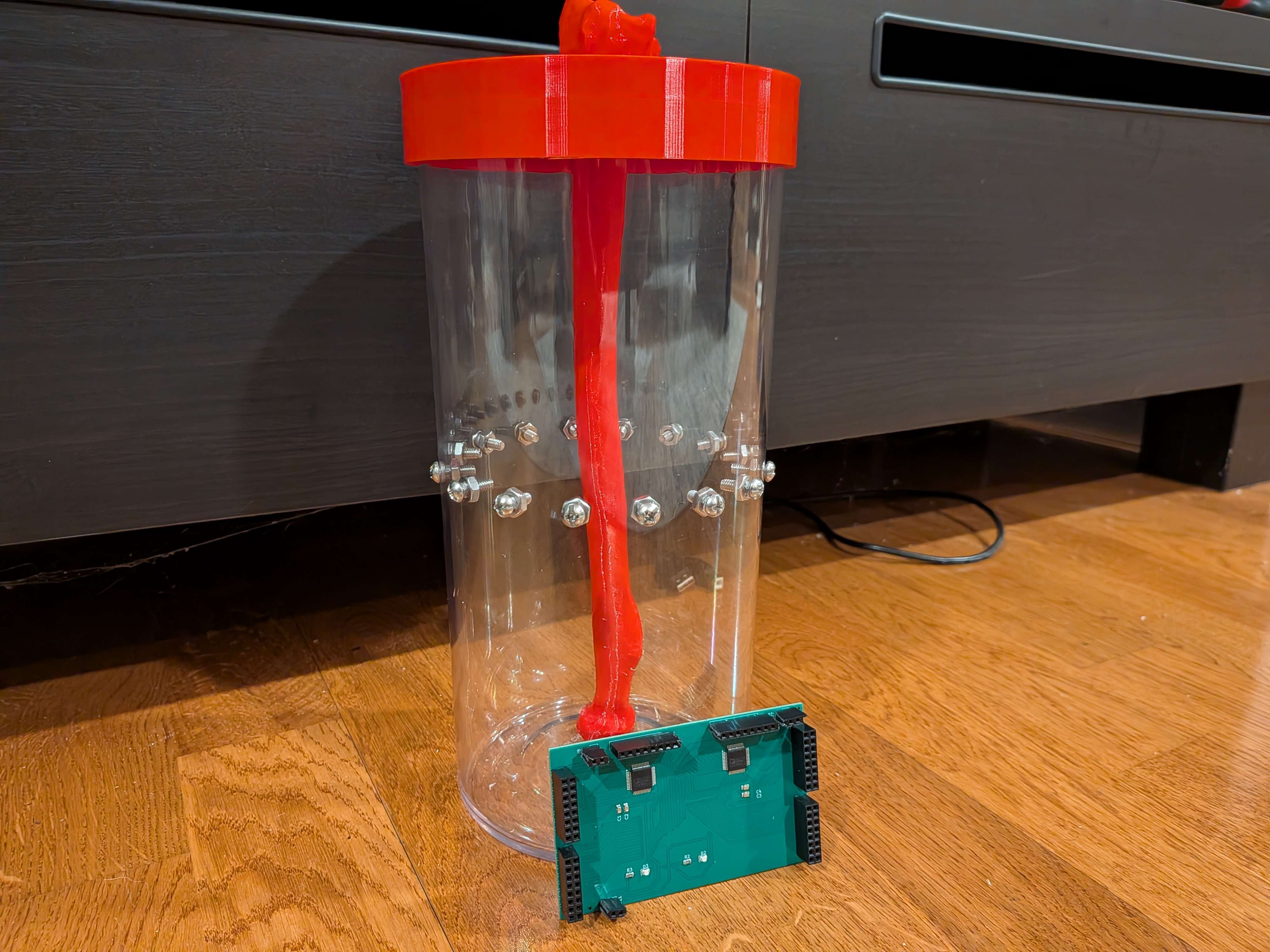
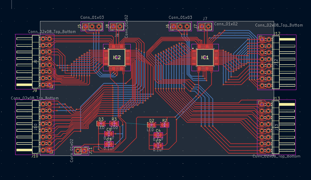
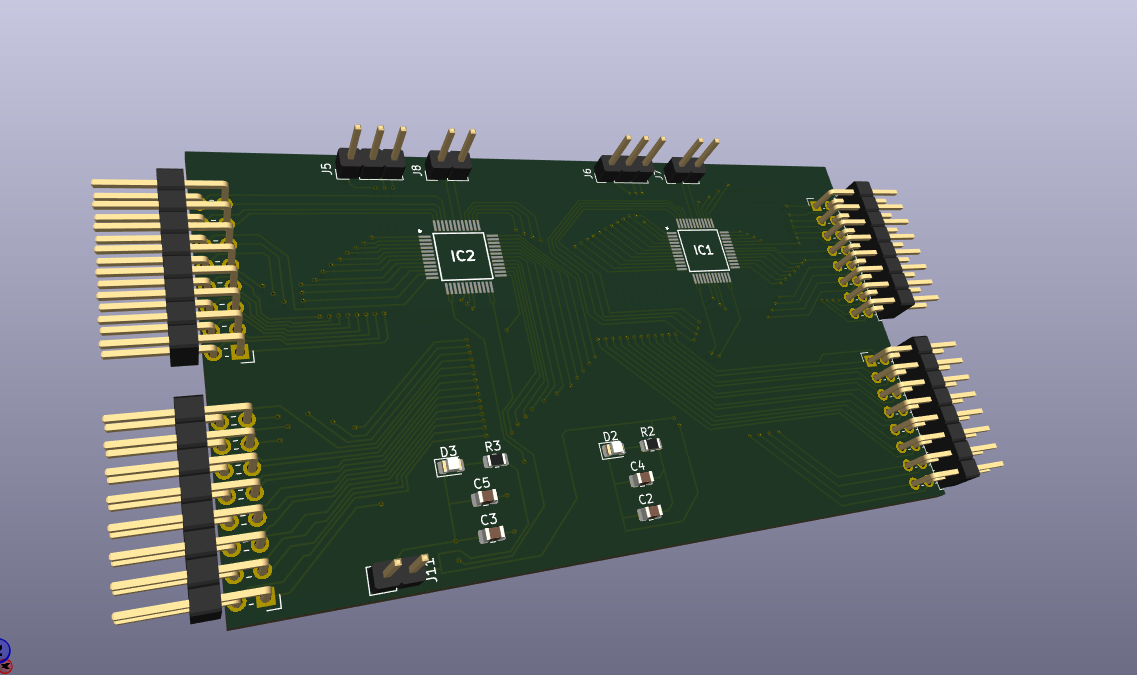
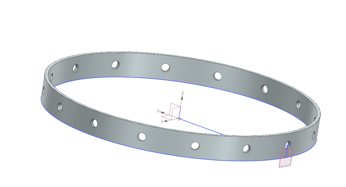
Hi all, it has been a minute since I have posted a dev-log, however I have been hard at work learning PCB design to build the front end hardware for the phantom MK2. Below are some photos of the PCB I have been building. Mind the mess of traces it is my first time. The following board utilizes 2 ADG725BSUZ chips to create a total of 4 16x1 muxes (2 for each chip). While researching I found that this specific chip had no compatible versions with breadboards, so I decided that it would be a good learning experience to design on my own. The components near the bottom of the board is just a simple light indicator that lets me know if the chips are getting power. One of the main reasons I decided to go with a custom board is I wanted to ensure the connection was stable among all of the 64 wires that will be running into the 16 electrode ring for the phantom MK2.

#PCB-Design#NewSkill#Prototype#EmbeddedHardware#dev-log

Phantom Mk2 and shipping delays

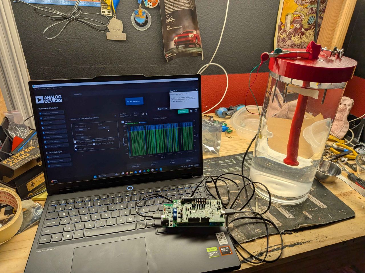
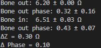
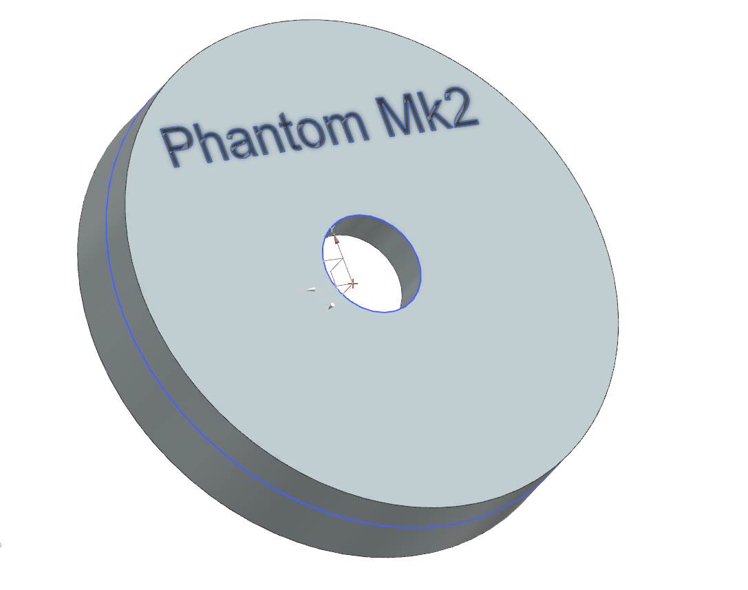
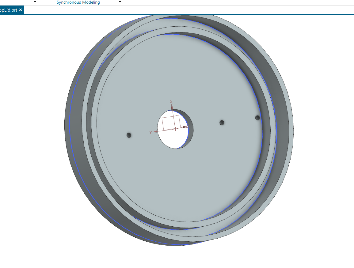
Attached is a photo of our first phantom design along with the data gathered. The setup is entirely custom, I 3d modeled the lid to hold 4mm thick steel rods that act as the electrodes and to fit onto a random glass vase I found in my house. This setup cannot produce any images as it was just a demonstration of a bone in vs bone out impedance test. It was mainly used as a learning opportunity to understand the data collection and the software I will be using for the upcoming test. The next phantom has already been printed, but will be much more complicated, as it will include 16 electrodes which require a 1:16 mux. We are currently in the process of custom printing PCB to be compatible with a breadboard for an easy prototyping process.

#3dPrinting#phantom-testing#prototype#CAD#dev-log

Phantom Mk2 and shipping delays

There has been progress made regarding the phantom testing, specifically the receptacles that are being used for the first phase phantom and the second phase phantom. I have received my deionized water solution and have made the saline mixture I plan on using for the phantom (0.9% saline solution), however there has been a delay in the alligator clips, I should have them in about 2 days. While waiting for the clips to arrive I have decided to begin the modeling and printing of the second phantom experiment. The first phantom is in a glass cylinder with 302 stainless steel rods protruding into the water from above, I will then use the metal alligator clips to read the data gathered from the electrodes. This is a vastly different approach to the second phantom model where I ordered an acrylic cylinder so I am able to drill holes in the side to act as the electrodes that would be used in an adjustable band. I am planning on using a 16 electrode ring for the second phantom model and will show more photos when I complete the model. However with the 16 electrode array requires me to build a mux using 2 ADG725 chips. More updates to come!

#3dPrinting#CAD#dev-log

Printing electrode mounts for phantom testing

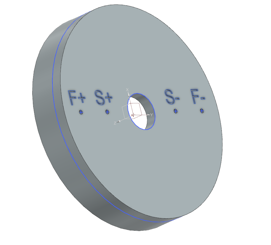
A lot has happened since the last entry, we ordered alligator clips that are compatible with our 4mm female connectors, this will allow us to connect the actual metal to the electrodes to get a reading of the conductivity levels of the saline solution and compare them to a bone in vs bone out. Speaking of metal, we also ordered a 1 1/2 foot 3mm long 316 stainless steel rod to use as electrodes, these electrodes will be mounted from the top of the tank using a 3d printed lid I designed (see the photos below) the hardware we bought has 4 electrode readers, F+, S+, S-, and F-. Even though this task seems very easy as we are basically sticking a multimeter into salt water, this test will allow me to become familiar with the analog digital software and our hardware stack that we are using, this will transform into creating a mux to support up to 16 (or maybe even 32) electrodes to produce images of the impedance values. As of now we are waiting on the alligator clips to arrive then we will begin testing.

#3dPrinting#CAD#dev-log

Video Promotion Material for EIT-tek

While I have been researching the type of electrodes to use, it occurred to me that this isn't going to be a cheap project. To solve this issue I have decided to begin reaching out to potential sponsors / investors of the project, to be successful in this feat, we must first make a promotion video / an elevator pitch to convey the severity and importance of this product. It will also help EIT-tek on social media platforms to achieve a small but recognizable presence. I am specifically interested in the Good Neighbor Fund I will be interviewing my own sister as she is one of the most incredible athletes I know. Additionally I might reach out to some coaches of mine or hers. I will keep you all updated!

#videography#filmmaking#dev-log

Repairing our 3D printer

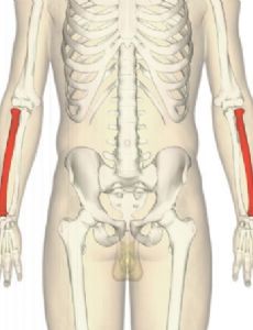
We have found some models on NIH 3D that would make good phantoms, specifically we have decided to model the Radius bone to measure bio impedance testing. (link to 3d model: here), an image has also been attached for reference. However while testing our 3d printer's leveling and filament dispersement, a part known to be a weakness of the Ender 3 v2 snapped in half, we have ordered the replacement part on and should continue with the phantom creation the following week.

#hardware#research#dev-log

Beginning Experimenting With Hardware

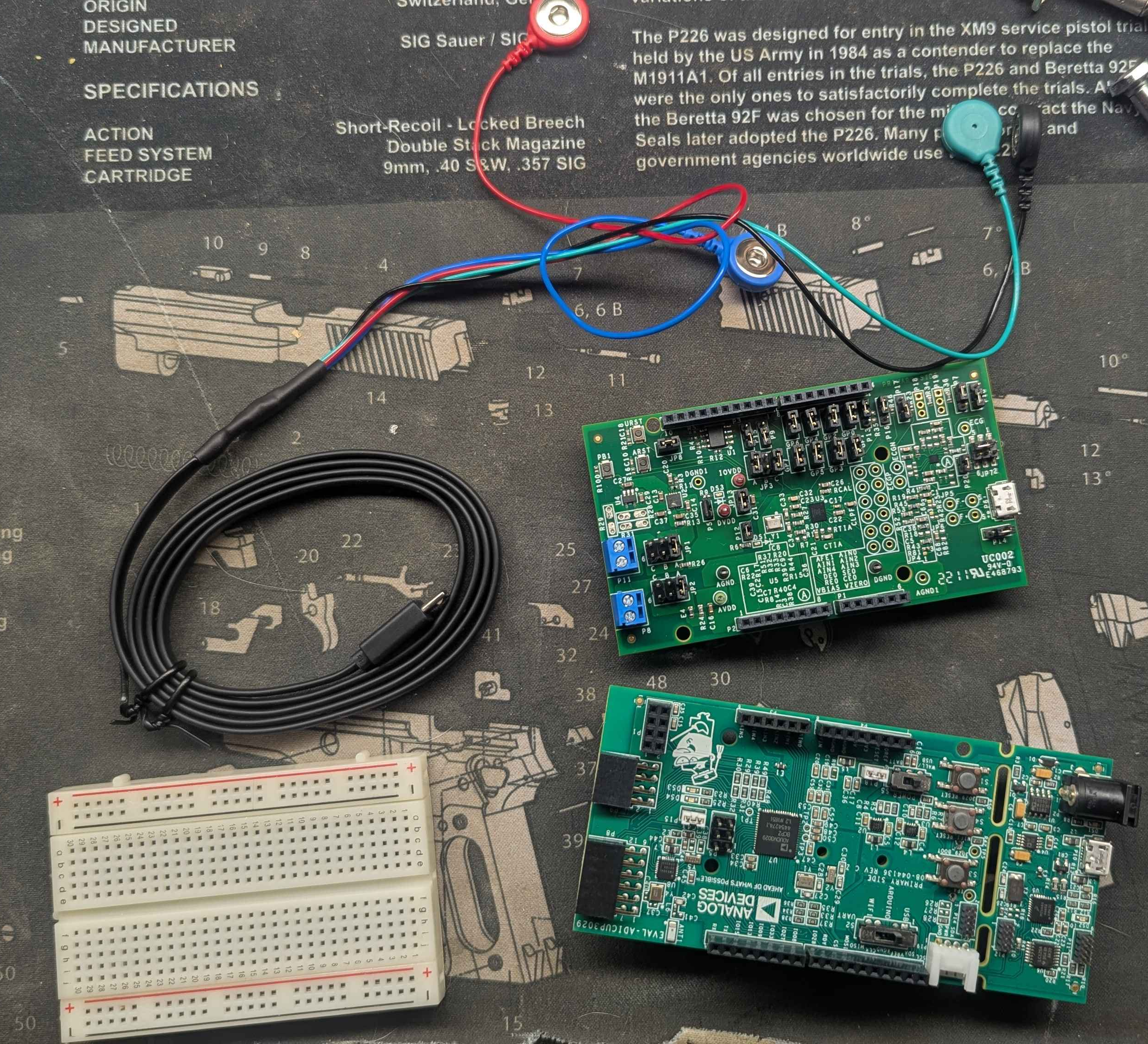
We have received our hardware from Analog Digital this past week and have begun setting up the software necessary to begin testing. The last couple of weeks have been slow as I recently had surgery on my right hand and have been recovering. Our first goal is to understand the bundled software with the analog digital hardware, specifically analog devices SensorPal. We also want to begin experimenting with phantoms as soon as possible, this means 3d printing a mock bone and placing it in a saline control tube to simulate a bone surrounded by blood. We will begin building researching electrode sensors to use for the phantom model.

#hardware#research#dev-log

committing to Alternative Hardware

Yesterday EIT-tek has committed and ordered our choice of hardware. We have decided to go with AN-1557 stack from analog digital. The following hardware is a major improvement and a more specialized stack for bio-impedance imaging. Analog digital has specific drivers for analyzing these signals, if you are interested in the hardware we will be using, click here. Compared to the Red Pitaya this hardware stack produces greater noise at 100dB compared to 80dB, effectively a 100 times better result than the Red Pitaya, (db scales logarithmically). The total cost of this hardware was about 600 dollars, we should receive this stack within the coming week. Additionally we plan on creating an analog mux in the frontend to allow us to create multiple channels of electrodes. More to come.

#hardware#research#dev-log

Researching Alternative Hardware

After our previous meeting with a researcher in the electrical impedance tomography field, we have had a lot to think about, I went into this project thinking the EIT-KIT from MIT was going to be the solution our imaging problems. However after doing further research we have decided to move forward with the Red Pitaya board for further testing. This device (specifically the Red-Pitaya STEMlab 125-14) offers us more customizable hardware, and higher dB readings than that of the EIT-KIT. Though substituting size for strength, we believe it can still be a portable, accessible, and cost effective imaging tool. Additionally this specific hardware has been referenced in multiple EIT papers. Though we will consult with professionals we believe this is the path EIT-tek will be heading.

#pivot#dev-log

Meeting with Veteran Electrical Impedance Imaging Researcher

Today EIT-tek met with a veteran electrical impedance tomography researcher to discuss the direction of our project and the realistic goals EIT-tek can achieve. This call taught us a lot, instead of utilizing the HHT (Hilbert Huang Transform) an algorithm that is particularly useful for analyzing signals whose spectral content changes in time. This algorithm provides an instantaneous frequency, which is already a known value in Electrical Impedance Imaging. Additionally we learned that in order to generate a good image you need a very high dB value. We will now be looking into a EIT/EIM hybrid approach which has been used in a clinical setting to assess changes in muscle architecture, specifically by reading the fluid buildup represented by edema.

#pivot#dev-log

Launching the public build log.

Going public with progress. The goal: treat this like a wet-lab notebook anyone can read. Trainers, clinicians, and investors shouldn't have to wait for a pitch deck to see what we're working on — they should be able to watch the prototype take shape, week by week.

Next up: finishing the 2D pyEIT mesh, filing the provisional patent, and running the first Hilbert-Huang pass on a clean reference signal to baseline the diagnosing before we touch the phantom.

#public-build#dev-log#transparency
No entries match that filter.